Hardware
 Knock Defender comes with:
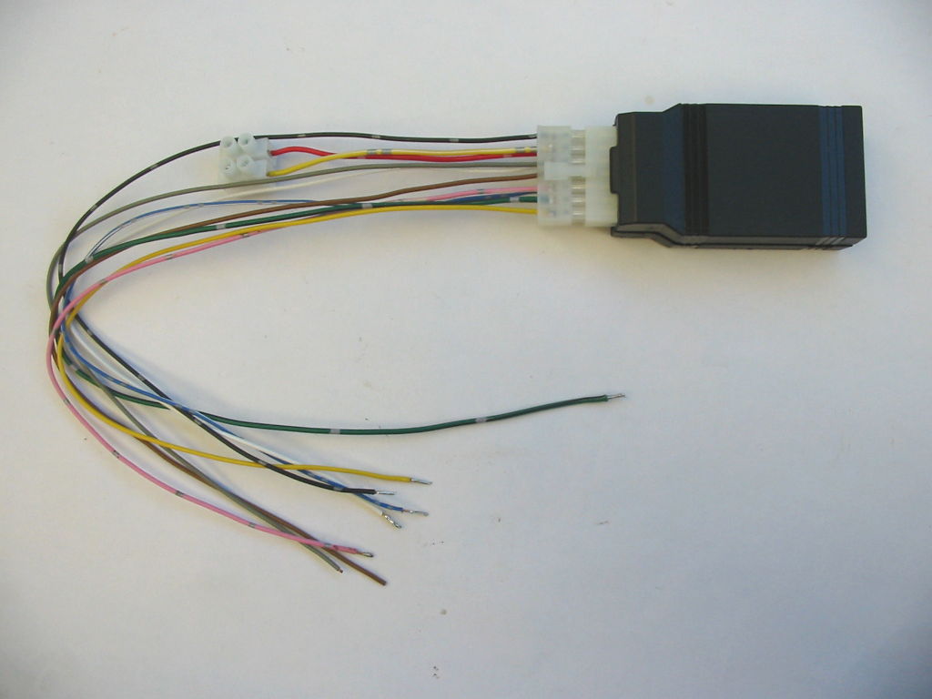
• Electronic hardware device, designed by David.
• USB-to-serial configuration cable with RJ45 end.
• Molex connector with automotive-grade wiring harness (500mm length).
• Heat-shrink tubing (300 mm in length), for permanent wired installation.
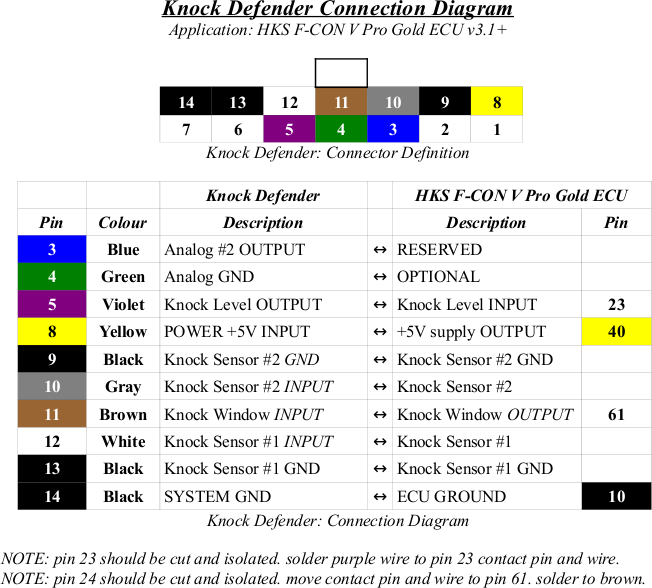
Connection Diagram
Knock Defender can be either connected directly to knock sensors, or can be spliced in between knock sensors and OEM ECU (for piggyback configuration as used by HKS F-CON V Pro).It is best to print this diagram (image is linked to pdf) so planning can be made on how to connect knock defender harness to the aftermarket ECU and engine harness.
When soldering knock defender harness wires to engine harness, DO NOT CONNECT knock defender box to its own harness during this process. Doing so may result in hardware failure.
Connection Diagram
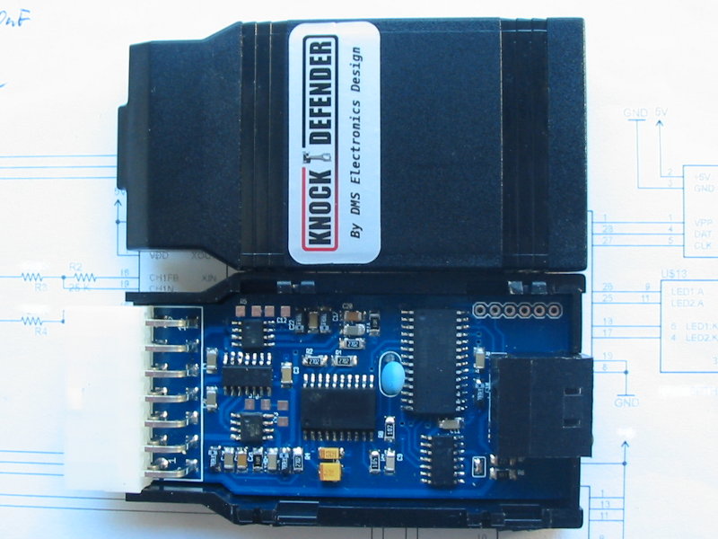
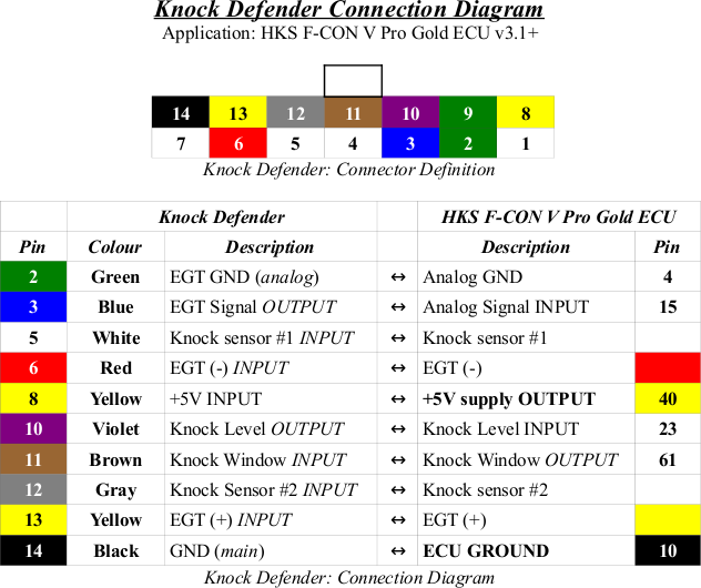
Knock Defender: Pre-release EGT-resonant-only version
A limited batch was designed and released. This is only for reference purposes only for those who purchased this particular variant. It does NOT feature hardware-based gain control, which is required for flat-response knock sensors. It works perfectly fine with resonant-based knock sensors, primarily used by Toyota and Mitsubishi vehicles.One added bonus is EGT-sensor support.
Connection diagram: [ pdf ] [ png ]
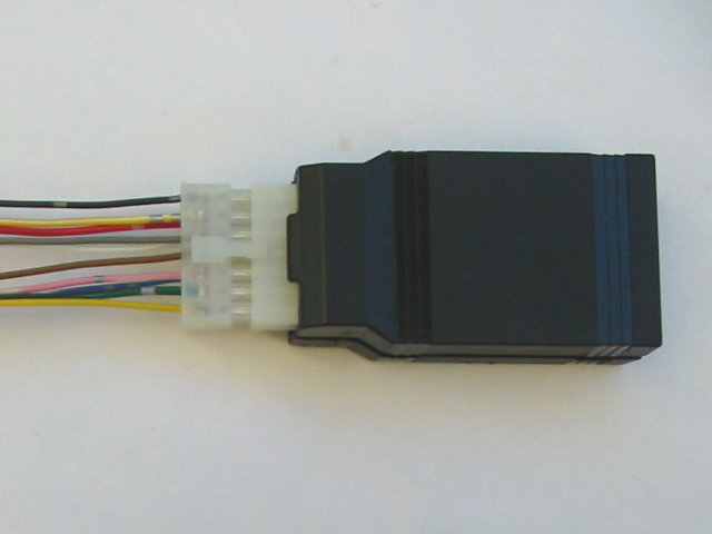
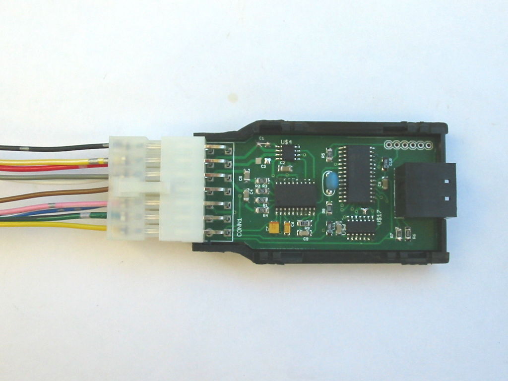
Photos: